

『Ge Panametrics Ultrasonic Flow Meter Manual PDF: Quick Setup and Configuration for Transducers』Related information(flow rotameter|digital flow meter|balo meter|hydraulic flow meter|volumetric meter|positive displacement meter|pitot tube flow meter|displacement meter|cfm meter|variable area flow meter|inline flow meter|differential pressure flow meter|calibrated flow meter|velocity meter|paddle wheel flow meter|oval gear flow meter|anemometer hvac|multiphase flow meter|doppler flow meter|thorpe tube flowmeter|heat flow meter)
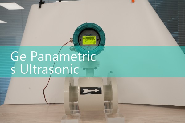
GE Panametrics Ultrasonic Flow Meter Manual PDF: Quick Setup and Configuration for Transducers
Quick Answer: The manual PDF for GE Panametrics ultrasonic flow meters covers transducer mounting, spacing, cable limits, signal strength, and velocity setup. Most instruments can be configured in 30 to 60 minutes when the pipe diameter, wall thickness, lining, and transducer type match the menu. Silver Automation Instruments can quote a compatible ultrasonic flow meter or spare transducers for your pipe size and process data.
What the GE Panametrics Manual PDF Covers
The PDF manual for GE Panametrics meters includes setup data for wetted and clamp-on transducers, cable length limits, signal thresholds, and velocity range settings. Common models such as the PT878, DF868, and XMT868 appear in service folders. The manual explains how to set pipe outer diameter, wall thickness, lining material, and sound speed for the fluid. It also shows how transducer spacing is calculated from the pipe geometry and fluid temperature.
Most engineers skip the part about cable spacing. In practice, signal cables run too close to VFD lines on many customer sites. The result is unstable readings and low signal strength after installation. The manual asks for a minimum distance of 300 mm from power cables. That one detail avoids hours of troubleshooting.
Quick Setup Steps for Transducers
First, measure pipe outer diameter with a tape. Do not trust the drawing. Old carbon steel pipes in chemical plants often have scale or coating that changes the true diameter. Next, enter the pipe material and lining in the setup menu. A 150 mm carbon steel pipe with 4 mm epoxy lining is different from a bare pipe.
Third, select the transducer frequency. For DN15 to DN50 use 2 MHz. For DN80 to DN300 use 1 MHz. For large pipes above DN400 use 0.5 MHz. Fourth, apply coupling compound and mount the transducers at the calculated spacing. The meter should show a signal strength above 60 and a sound speed within 2 percent of the expected value. Fifth, set the flow units to kg/h or m3/h. Do not leave the unit in feet per second if the customer wants mass flow.
Transducer Configuration Parameters That Matter
The critical values are path length, axial distance, fluid sound speed, and signal gain. On a PT878 portable meter, the setup menu asks for transducer part number. If you pick the wrong number, the meter calculates the wrong spacing. In practice, we have seen a food plant in Vietnam enter 160 mm for a 150 mm pipe. The readings were off by 7 percent until the value was corrected.
Check the units before saving. The manual uses metric and imperial options. For water with 0.5 to 3 percent solids, the sound speed changes with temperature and particle load. A chemical batch reactor in Monterrey had unstable readings because viscosity changed from 200 cP to 900 cP during the batch. The clamp-on meter needed a lower transducer frequency and a longer damping time.
Common Field Issues and Fixes
Low signal is the top issue. In a desalination plant in Perth, signal strength dropped below 30 because the pipe surface had salt scale. The fix was cleaning to bare metal and adding more couplant. After that the signal returned to 65. Another site in Saudi Arabia tied transducer cables next to VFD cables. The readings jumped by 8 percent. The plant moved the signal cables 400 mm away and the reading stabilized.
If the meter shows negative flow, sw
Replacement Options from Silver Automation Instruments
Silver Automation Instruments supplies industrial ultrasonic flow meters, including clamp-on, insertion, and inline types for water, wastewater, chemicals, and food liquids. We do not sell original GE Panametrics spare parts. But we can quote a compatible Silver Instruments ultrasonic flow meter or spare transducer for your process. Send us your pressure (bar), temperature (°C), pipe size (DN), and flow range. We reply with model, price, and datasheet within 24 hours.
Our contact details are below.
Tel: +86-25-68650347
Whatsapp: +86-25-52155837
WeChat: +86 15365082610
Recommended Models for Common Pipe Sizes
For clean water from DN15 to DN600, many customers choose the Silver Instruments SUL-100 series clamp-on ultrasonic flow meter. For wastewater with 0.5 to 3 percent solids, the insertion type works better. For chemical dosing with low flow rates down to 0.1 m/s, use an inline ultrasonic flow meter with PT100 temperature input. For ATEX Zone 1 sites, specify the Ex d version and use a 4-20 mA HART output. These are not direct GE Panametrics parts but they cover the same pipe range and common process conditions. We have supplied these meters to water treatment plants in the Philippines, a dairy in New Zealand, and a mining site in Ghana.
FAQ
1. Where can I download the GE Panametrics ultrasonic flow meter manual PDF?
Check the Baker Hughes or GE measurement manual library for the specific model such as PT878, DF868, XMT868, or CTF878. Many local distributors also keep the PDF on file. If you have a Silver Instruments meter, request the quick start guide directly from our sales team.
2. How do I configure transducers for a clamp-on installation?
Enter the pipe outer diameter, wall thickness, lining material, fluid type, and transducer frequency. The meter calculates spacing. Mount the transducers with couplant and check signal strength and sound speed. A signal above 60 is usually acceptable for clean water.
3. What is the minimum straight pipe length?
Use at least 10 diameters upstream and 5 diameters downstream for a single path clamp-on meter. If the installation has a pump, elbow, or partially open valve, use 20 diameters upstream. This is called fully developed flow and prevents swirl errors.
4. Can I use a GE Panametrics manual for other ultrasonic flow meter brands?
The general setup steps are similar for many transit time ultrasonic meters. But the menu names and transducer part numbers are different. Do not enter GE transducer codes into another brand. Contact Silver Instruments for a setup sheet that matches your model.
5. What output signals are available?
Most industrial ultrasonic flow meters support 4-20 mA, pulse, and RS485 Modbus. Some versions support HART. Specify the output when you order because the terminal wiring is different. For hazardous areas, the Ex d versions have specific cable glands.
For a quote, call +86-25-68650347 or WhatsApp +86-25-52155837.
 Hot News
 Related AD